CT60CT200CT1000CT2000A ACDC Current Sensor Circuit Diagram
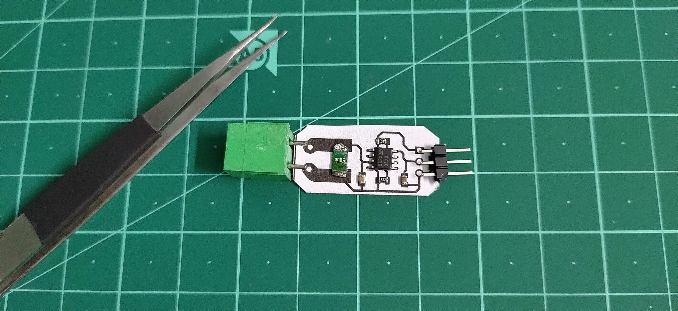
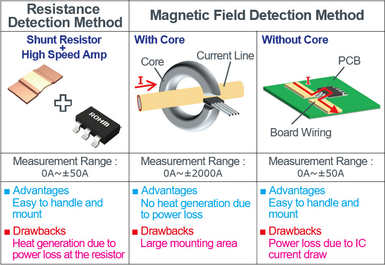
CT60CT200CT1000CT2000A ACDC Current Sensor Circuit Diagram Ways to measure current: 1- Indirect method: such as current transformers (in the figure) and Hall effect sensors, which relies on Faraday's law of induction to sense current in a circuit and convert it to a proportional voltage. These methods are suitable more for high current systems. 2- Direct method: which relies on Ohm's law which states that V = I x R.

Flux Gate Sensor Current Sensing Method. A saturable Inductor is the main component for the Fluxgate sensing technique. Due to this, Fluxgate sensor is called as Saturable Inductor Current Sensor. The inductor core which is used for the fluxgate sensor works in the saturation region.
Current Sensing Techniques using Different Current Sensors Circuit Diagram
Acs712 current sensor can measure both direct and alternating current. For this post/tutorial/project I am going to measure only dc current. Formula which i derived and explained in the tutorial is only for direct current measurement. You can not use the below formula to measure alternating current with acs712 hall effect current sensor.

The typical current of such a circuit would be at around 0.020A. Since the smallest current range of the ACS712 is 5 Ampere, you will not get much of a signal on the sensor output. In this tutorial, we explored how to use the ACS712 current sensor with an Arduino to measure both DC and AC currents. By understanding the working principle of
An Engineer's Guide to Current Sensing (Rev. B) Circuit Diagram
Hall effect current sensor circuit Using Arduino helps to monitor and log current flow to a device. Here the ACS712 current sensor ic placed in a breakout board and connect with Current sense target load and Micro-controller. The sensor detects current flow through IP+ and IP- pins (Resistance Current Conductor), it creates hall effect and then proportional voltage output taken form pin 7 Introduction to Current Sense Amplifiers 4 Integrating the Current Sensing Signal Path 6 Integrated, Current Sensing Analog-to-Digital Converter 8 Integrating the Current Sensing Resistor 11 Common uses for Multi-Channel Current Monitoring 13 2. Out-of-range current measurements with current-sense amplifiers Measuring Current to Detect Out-of-Range